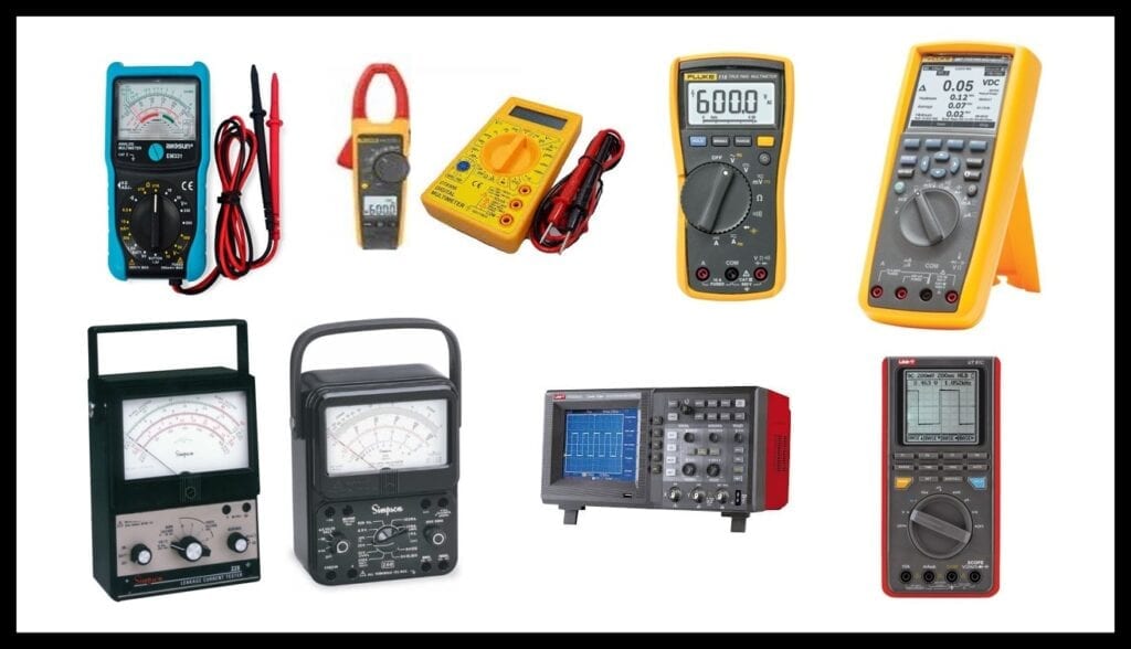
Electrical measuring instruments (Ohmmeter, Ammeter, Voltmeter)
For every hobbyist, student of electricity, electronics or related fields, the dream is to have their own measuring instruments. In some cases, trainees acquire very poor quality instruments that, instead of helping them learn, complicate failures or show false measurements.
In other cases, the apprentices acquire instruments of very high quality but, having no experience, they make the wrong connections, resulting in a mismatch or failure of the instrument. Throughout this article we are going to show its correct use, applications and verification of its calibration.
What are electrical measuring instruments?
To carry out a study of electrical signals we have to measure them and, of course, record them. It is very important for anyone who wants to analyze these phenomena to have reliable electrical measuring instruments.
Measurements are made based on electrical parameters, according to their properties such as pressure, flow, force or temperature. In this article we will dedicate ourselves to studying the measurement instruments for the most common basic parameters such as:
- THE Ohmmeter.
- THE Ammeter.
- The Voltmeter.
What is an Ohmmeter?
It is an instrument for measuring electrical resistance. Using the relationship between the potential difference (Voltage) and electric current intensity (Amps) developed by Ohm's law.
By the way, you might be interested in seeing later What does Ohm's law and its secrets state?

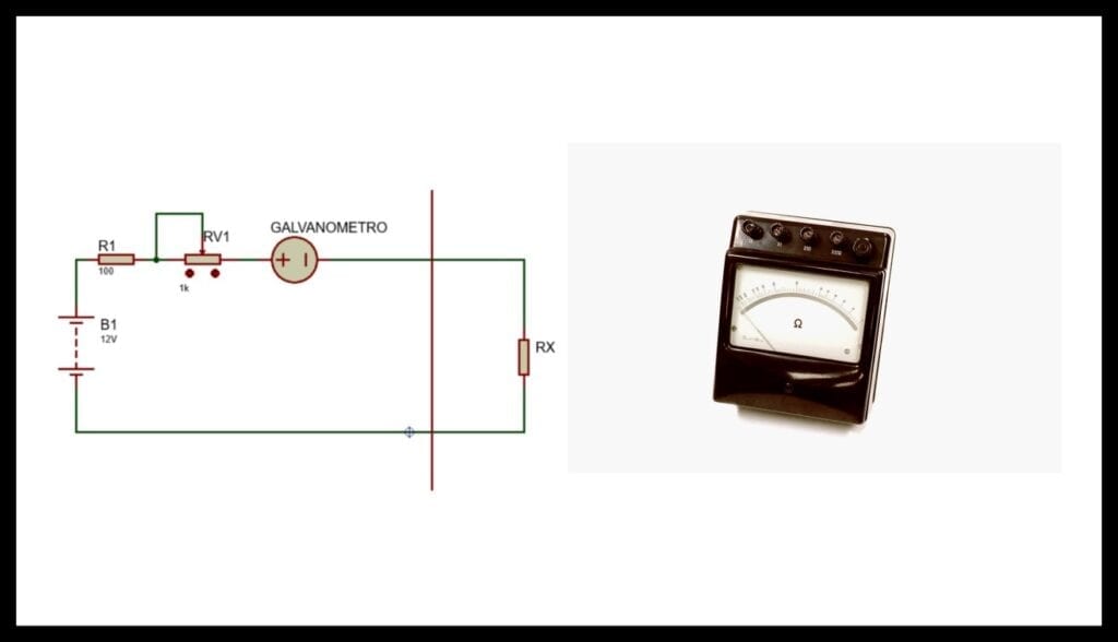
The Analog Ohmmeter:
Use a galvanometer, which is an electrical current meter. That works like a transducer, receiving the electric current with a constant voltage causing alterations in a pointer that indicates the measurement through a relationship that is calculated by Ohm's law. (See Ohm's law article). Watch Figure 2
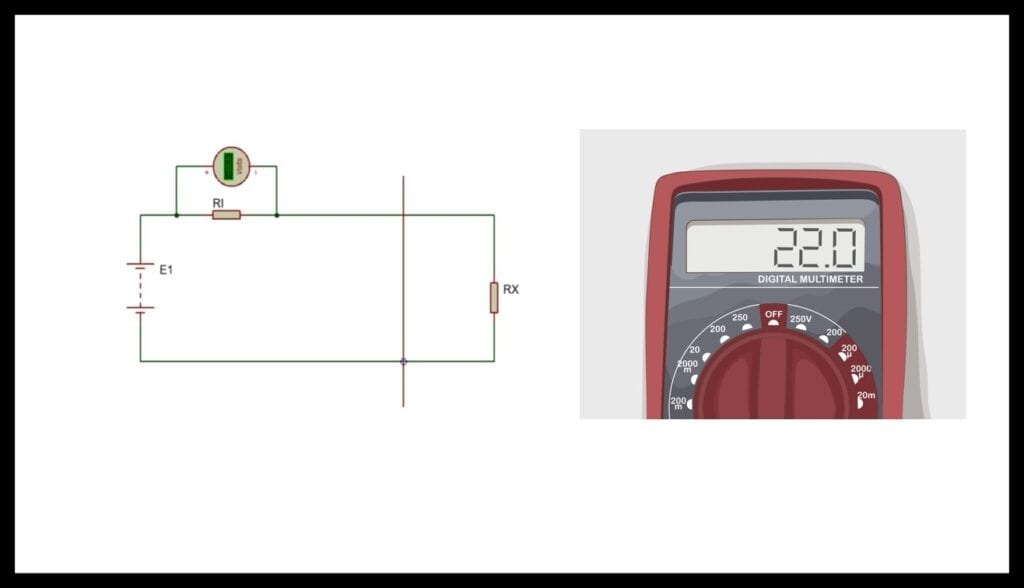
The Digital Ohmmeter:
In this case you do not use the galvanometer, instead use a relationship with a voltage divider (which depends on the scale) and a signal acquisition (Analog / digital) taking the value of the resistance by the Ohm's law relationship. See figure 3
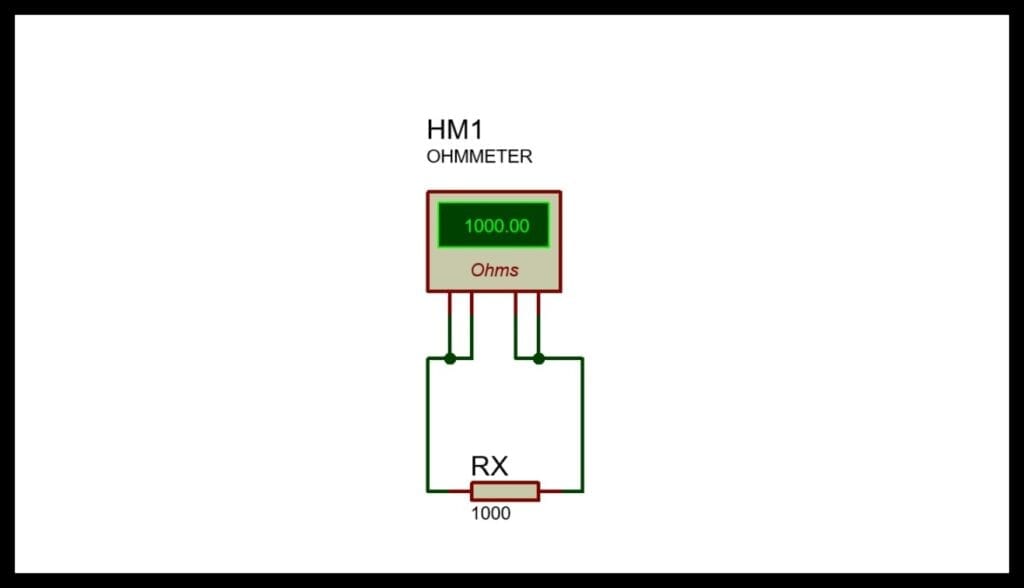
Ohmmeter connection:
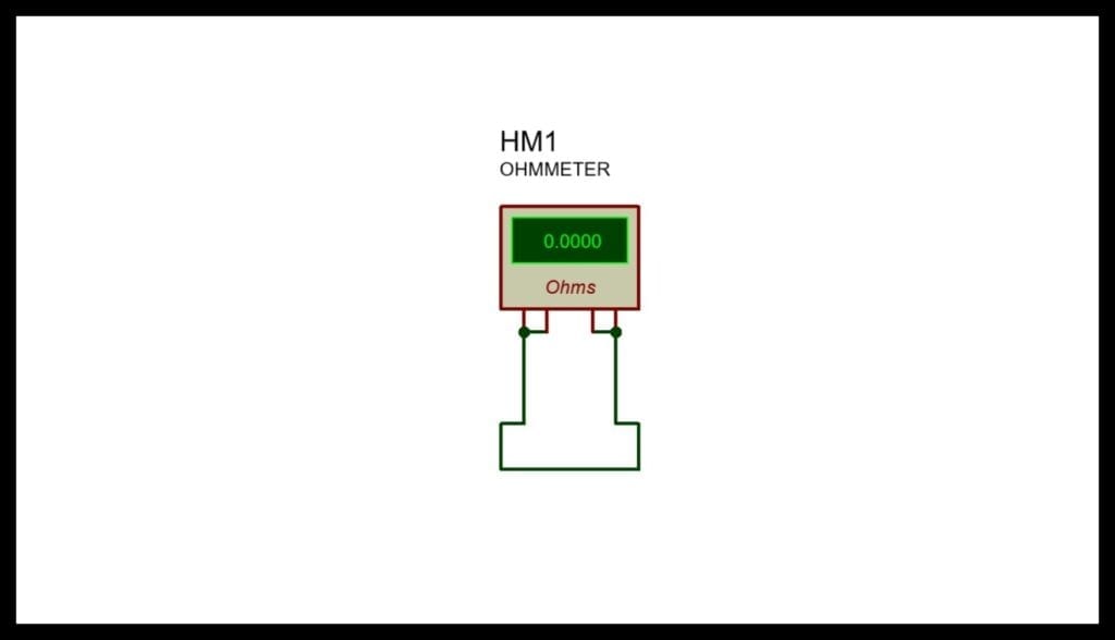
The Ohmmeter is connected in parallel to the load (see figure 4), it is recommended that the tip of the instrument is in optimal conditions (Sulphated or dirty tips cause measurement error). It is important to note that the supply of the potential difference is carried out by the internal battery of the instrument.
Steps to perform a correct measurement with electrical measuring instruments:
We recommend that you perform the following steps to obtain better results in your measurements:
Calibration and test lead check:
In analog instruments it was an obligation to perform a calibration and check of the tips, but in digital instruments that in theory is automatic, there are factors that this calibration can, instead of automating (if everything is not correct), produce misalignment or error in the measurements. We recommend performing every time we need a measurement, verify the calibration of the instrument:
Tip check:
This step is very basic but elementary to obtain readings with a lower margin of error (we recommend doing it frequently), they only consist of joining the tips of the instrument forcing a measurement of +/- 0 Ω as shown in figure 5
It should be emphasized that obtaining as a result in this 0 Ω calibration is ideal, it should be remembered that the measuring tips use copper cables (in theory excellent conductors) but in practice all conductors have some resistance, just like the tips (they are usually made of stainless steel, the professional ones are made of copper with a silver bath), however they do not justify a result greater than 0.2 Ω +/- the percentage (%) of the reading precision of the instrument.
To give a high value we recommend: clean the tips, check the calibration of the instrument and the most critical point, the condition of the instrument's battery.
Instrument Calibration Check:
For this test we recommend having a standard, for example, a 100 Ω resistor with a tolerance no greater than +/- 1% in other words:
R Max = 100 Ω + (100Ω x 0.01) = 101 Ω
R min = 100 Ω - (100Ω x 0.01) = 99 Ω
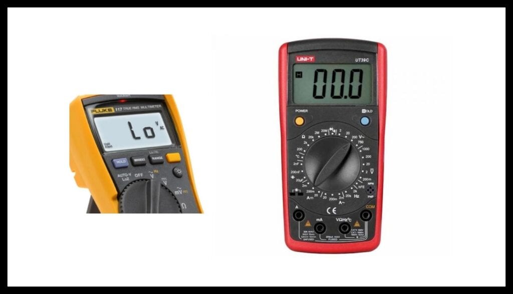
Now if at this point we add the instrument reading error (it depends on the brand and quality of the Ohmmeter), usually a Fluke model 117 digital instrument on the auto range scale (0 - 6 M Ω) is +/- 0.9 % [2], so we can have the following range of measures:
R Max = 101 Ω + (101Ω x 0.009) = 101,9 Ω
R min = 99 Ω - (99Ω x 0.009) = 98,1 Ω
Of course, this result is relative, since the environmental conditions (a very important point for calibration with standards) and the zero error were not considered, but despite all these factors we must have an approximate value to the standard.
If you do not use an auto ranging instrument, it is advisable to place it in the measurement range closest to the standard.
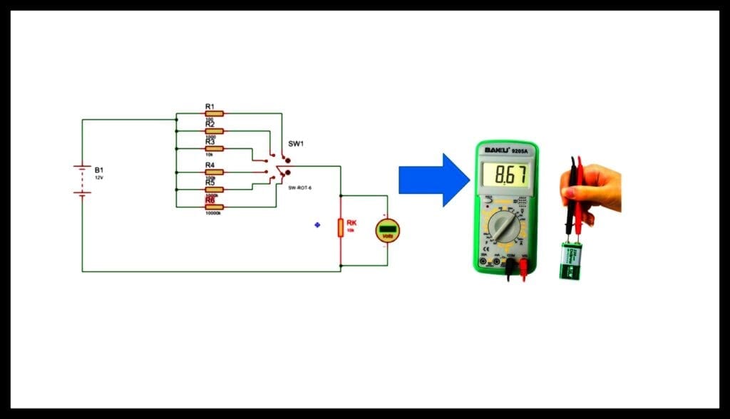
In figure 6 we see 2 multimeters (it is an all-in-one instrument) in this case the fluke 117 is auto-ranging and the UNI-T UT38C you have to select the scale closest to the pattern. For example, the multimeter brand UNI-T model UT-39c [3] for this check is recommended 200 Ω
Precautions when using the Ohmmeter as an electrical measuring instrument:
For the correct use of this measuring instrument we recommend the following points:
- To carry out measurements with the Ohmmeter you must have the power supplies disconnected.
- As it was already detailed in the previous point, the test leads check and the calibration check must be carried out before the measurement.
- To obtain a correct measurement, it is advisable to disconnect at least one terminal of the resistance or component, thus avoiding any impedance in parallel.
It may interest you: The Power of Watt's Law
What is the Ammeter?
The ammeter is used to measure the intensity of electrical currents in a branch or node of the electrical circuit.
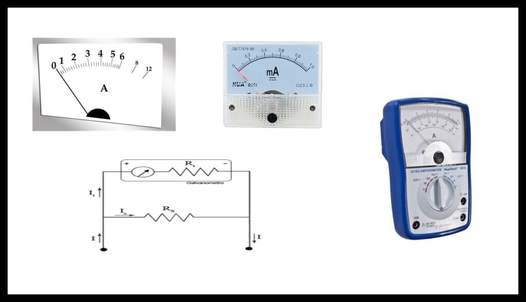
The analog Ammeter:
The ammeters have an internal resistance called shunt (RS), generally it is below 1 ohm of high precision, its purpose is to reduce the electrical current intensity of the node connecting in parallel to the galvanometer. See figure 7.
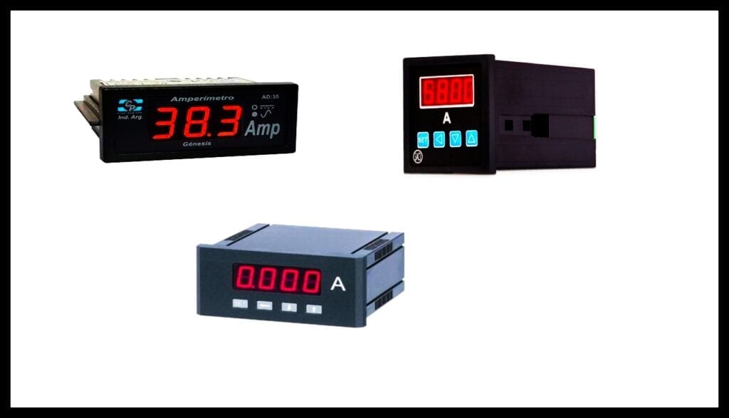
The digital ammeter:
Like the parallel ammeter, it uses a shunt resistance proportional to the scale, but instead of using a galvanometer, a signal acquisition (analog / digital) is performed, it generally uses low-pass filters to avoid noise.
Steps to carry out a correct measurement with the Ammeter as an electrical measuring instrument:
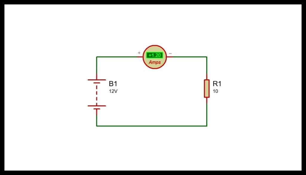
- The ammeter is connected in series (with a jumper) to the load as shown in figure 9
- It is advisable to make the connections with the power source turned off by placing the ammeter on the Maximum scale and lowering the scale until reaching the recommended scale.
- It is always recommended to check the status of the Battery and fuses before taking any measure.
Precautions when using the Ammeter as an electrical measuring instrument:
- It is important to remember that the Ammeter depends on the shunt resistance in parallel in other words the internal impedance tends to be 0 Ω in theory (in practice it will depend on the scale) but it is usually less than 1 Ω so it should never be connected in PARALLEL.
- It is very important to check the protection fuse and never set a value higher than the recommended one.
What is the Voltmeter?
El Voltmeter is an instrument used to measure the potential difference between two points in an electrical circuit.
The analog voltmeter:
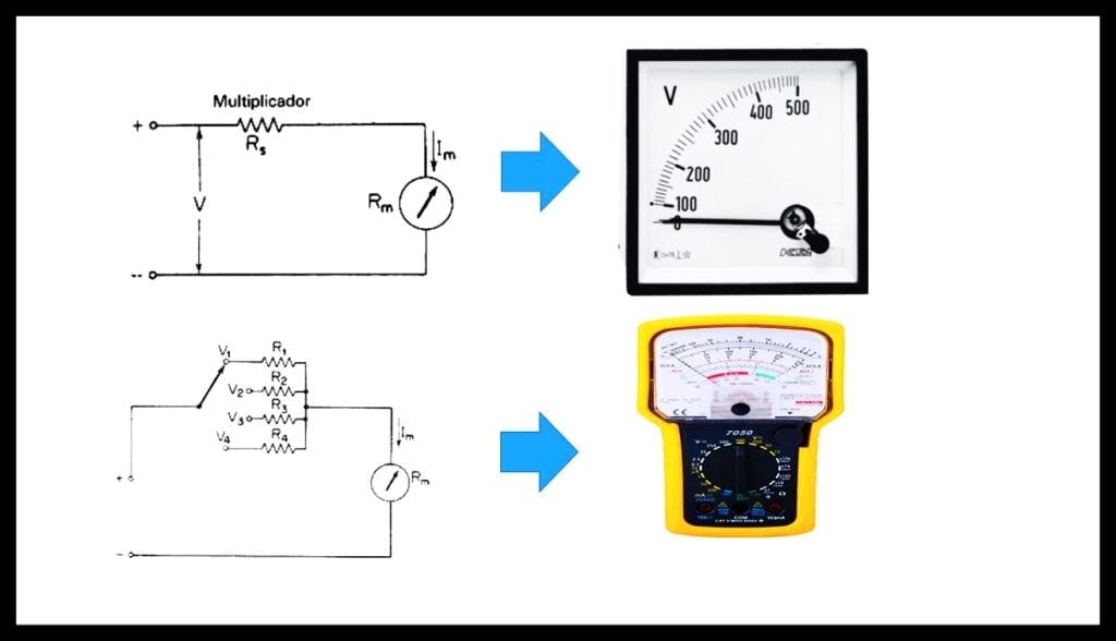
It consists of a galvanometer with a series resistance where its value will depend on the selected scale, see figure 10
The Digital Voltmeter:
The digital voltmeter has the same principle as the analog voltmeter, the difference being that the galvanometer is replaced by a resistance, making a voltage divider circuit with a proportional relationship.
Voltmeter Connection:
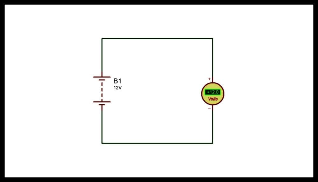
Voltmeters have a high impedance in theory they tend to be infinite in practice they have on average 1M Ω (of course it varies according to the scale), their connection is in parallel as shown in figure 12
Steps to perform a correct measurement with the Voltmeter as an electrical measuring instrument:
A. Always place the Voltmeter on the highest scale (for protection) and progressively lower to the nearest scale higher than the measurement.
B. Always check the status of the instrument's battery (with a discharged battery it produces measurement errors).
C. Check the polarity of the test leads, it is recommended to respect the color of the test leads (+ Red) (- Black).
D. In the case of negative, it is recommended to fix it to (-) or circuit ground and vary the test lead (+).
E. Verify if the desired voltage measurement is DC (Direct current) or AC (Alternating current).
Precautions when using the Voltmeter as an electrical measuring tool:
Voltmeters generally have a relatively high scale (600V - 1000V) always start reading on this scale (AC / DC).
We remember that the measurements are in parallel (in series it would cause an open circuit) see ohm's law topic.
Final Recommendations for Electrical Measurement Instruments
For any fanatic, student or technician in the areas of electronics, electricity it is essential to know how to use measuring instruments, their calibration is necessary to carry out diagnosis and technical evaluations. In the case that you use a multimeter take as usual the check of the Ohmmeter calibration, since in these instruments (all in one), all the parameters are somehow interconnected for example (battery, tips, ammeters and voltmeter for measurement of resistance variables among others).
The use of test pattern for the electrical measurement instruments Ohmmeter, Ammeter and Voltmeter is necessary to do it constantly due to our experience of not doing it and unfortunately having the instrument out of calibration, can give us false signals of failures or reading errors.
We hope that this introductory article to the subject is helpful, we await your comments and doubts.