The Power of Kirchhoff's Laws
“Gustav Robert Kirchhoff (Königsberg, March 12, 1824-Berlin, October 17, 1887) was a German physicist, whose main scientific contributions to the well-known Kirchhoff laws focused on the fields of electrical circuits, the theory of plates, optics, spectroscopy, and the emission of blackbody radiation.” [1]
"Kirchhoff's Laws" [2] are considered the voltage and current relationships between the different elements of an electrical network.
They are two simple laws, but "powerful", since together with the Ohm's law They allow solving electrical networks, this is to know the values of the currents and voltages of the elements, thus knowing the behavior of the active and passive elements of the network.
We invite you to see the article of Ohm's law and its secrets
BASIC CONCEPTS from Kirchhoff's law:
In an electrical network, the elements can be connected in different ways according to the need and utility of the network. For the study of networks, terminology such as knots or nodes, meshes and branches are used. See figure 1.
Electric Network In Kirchhoff's law:
Circuit composed of different elements such as motors, capacitors, resistance, among others.
Node:
Point of connection between the elements. It is symbolized by a dot.
Foliage:
The branch of a network is the conductor through which an electric current of the same intensity circulates. A branch is always between two nodes. The branches are symbolized with lines.
Mesh:
Road closed in a circuit.
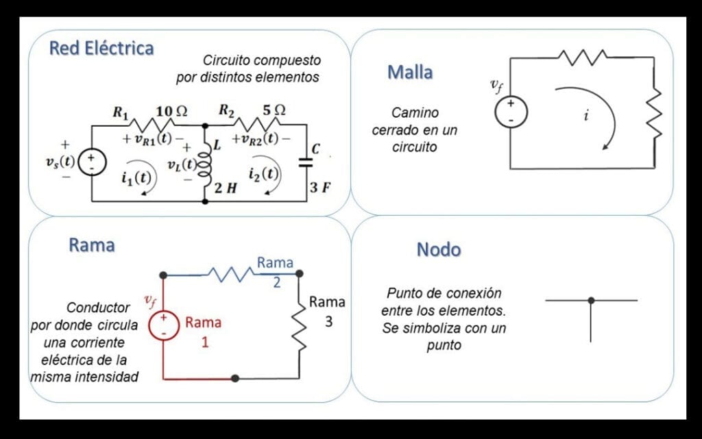
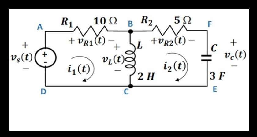
Figure 2 shows an electrical network with:
- In figure 2 (a) two meshes: the first mesh doing the ABCDA route, and the second mesh doing the BFECB route. With two (2) Node at point B and the common DCE point.
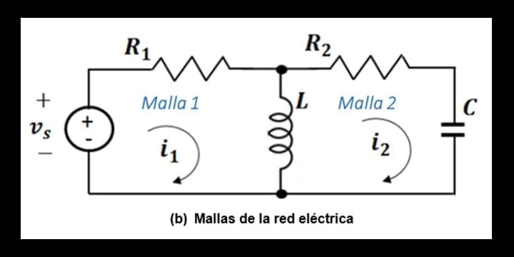
- In figure 2 (b) you can see meshes 1 and 2.
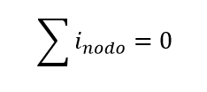
-KIRCHOFF'S FIRST LAW "Law of Currents or Law of Nodes"
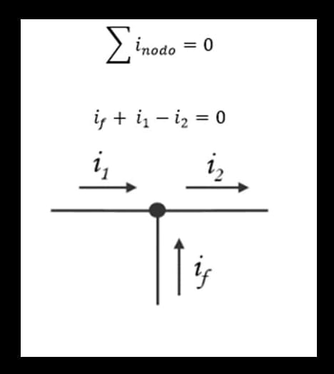
Kirchhoff's First Law establishes that "The algebraic sum of the current intensities in a node is zero" [3]. Mathematically it is represented with the expression (see formula 1):
To apply the Kirchhoff's Current Law are considered “positive” the currents entering the node, and "negative" currents leaving the node. For example, in figure 3 there is a node with 3 branches, where the currents (if) and (i1) are positive since they enter the node, and the current (i2), which leaves the node, is considered negative; Thus, for the node in Figure 1, Kirchhoff's current law is established as:
Note - algebraic addition: is a combination of addition and subtraction of whole numbers. One way to do algebraic addition is to add the positive numbers apart from the negative numbers and then subtract them. The sign of the result depends on which of the numbers (positive or negative is greater).
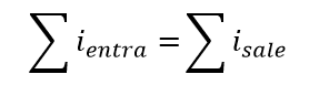
In Kirchhoff's Laws, The first law is based on the law of conservation of charge, which states that the algebraic sum of electrical charges within an electrical network does not change. Thus, no net charge is stored in the nodes, therefore, the sum of the electrical currents that enter a node is equal to the sum of the currents that leave it:
Maybe you may be interested: The Power of Watt's Law
-KIRCHHOFF'S SECOND LAW "Law of Tensions”
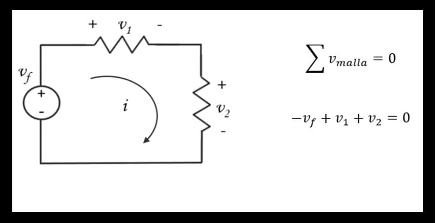
Kirchhoff's Second Law states that "the algebraic sum of the stresses around a closed path is zero." [3]. Mathematically it is represented with the expression: (see formula 3)
Figure 4 shows an electrical network with a mesh: It is established that a current "i" circulates in the mesh in a clockwise direction.
-SOLVING EXERCISES WITH KIRCHHOFF'S LAWS
General procedure
- Assign a stream to each branch.
- Kirchhoff's current law is applied at the nodes of the circuit minus one.
- A name and polarity are placed on the voltage of each electrical resistance.
- Ohm's law to express voltage as a function of electric current.
- The meshes of the electrical network are determined and Kirchhoff's Voltage Law is applied to each mesh.
- The system of equations obtained by the substitution method, Cramer's rule, or another method is solved.
SOLVED EXERCISES:
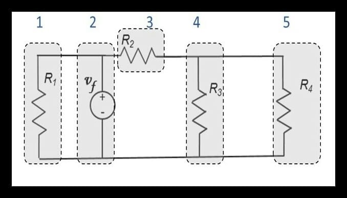
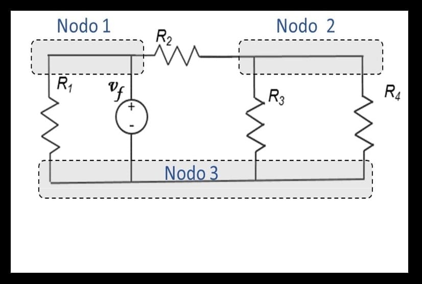
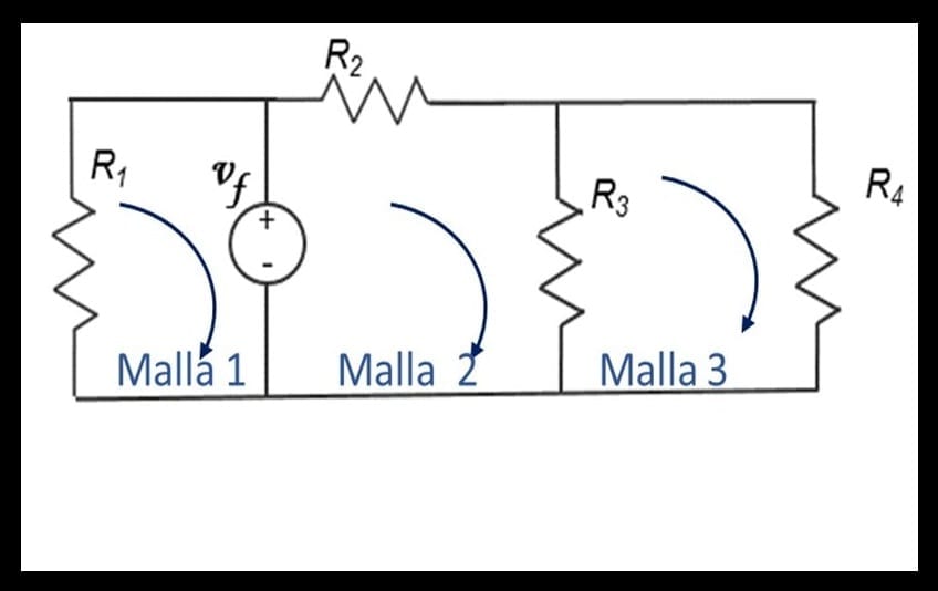
Exercise 1. For the electrical network indicate:
a) Number of branches, b) Number of nodes, c) Number of meshes.
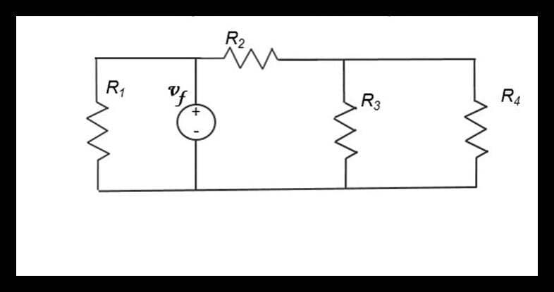
Solution:
a) The network has five branches. In the following figure each branch is indicated between dotted lines each branch:
b) The network has three nodes, as shown in the following figure. The nodes are indicated between dotted lines:
c) The network has 3 meshes, as shown in the following figure:
Exercise 2. Determine the current i and the voltages of each element
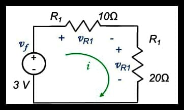
Solution:
The electrical network is a mesh, where a single intensity of current circulates that is designated as "i". To solve the electrical network apply the Ohm's law on each resistor and Kirchhoff's voltage law on the mesh.
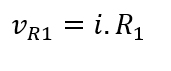
Ohm's Law states that voltage is equal to electric current times the value of resistance:
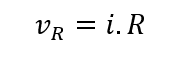
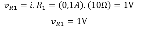
Thus, for the resistor R1, the voltage VR1 is

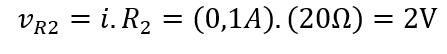
For resistance R2, the voltage VR2 is
Applying Kirchhoff's Voltage Law on the mesh, traveling clockwise:
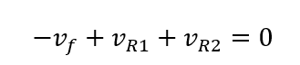
Substituting these voltages we have:
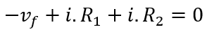
The term is passed with a positive sign to the other side of the equality, and the current intensity is cleared:
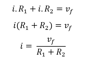
The values of the voltage source and electrical resistances are replaced:
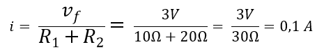
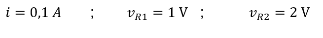
The intensity of current flowing through the network is: i=0,1A
The voltage across resistor R1 is
The voltage across resistor R2 is
Result:
CONCLUSIONS to Kirchhoff's law
The study of Kirchhoff's Laws (Kirchhoff's current law, Kirchhoff's voltage law), together with Ohm's Law, are the fundamental bases for the analysis of any electrical network.
Using Kirchhoff's Current Law, which states that the algebraic sum of the currents in a node is zero, and the Voltage Law, which states that the algebraic sum of the voltages in a mesh is zero, the relationships between currents and voltages are determined. in any electrical network of two or more elements.
Con el amplio uso de la electricidad en la industria, comercio, hogares, entre otros, las Leyes de Kirchhoff se utilizan diariamente para el estudio de infinidades de redes y sus aplicaciones.We invite you to leave your comments, questions or request a second part of this very important KIRCHOFF LAW and of course you can see our previous posts like Electrical measuring instruments (Ohmmeter, Voltmeter and Ammeter)